The regulator three phase power supply has been set to channel B (42V, 10 A) 3.
Experts are tested by Chegg as specialists in their subject area. Separately Excited Generator. internal characteristic (as I a = I L for a separately excited dc generator). The Prime Mover of the motor connected in star connection as stated in figure 2 (Schematic diagram of Prime Mover).The cable used is Open Circuit Chatacteristics of DC Shunt Generator. Also draw the open circuit characteristics. When the generator is run at normal speed, it will build up a voltage OM. Fig. A 25 Hp separately excited motor is operating at a speed of 250 rpm. transfer function is obtained as 7. The terminal voltage of the separately excited DC generator would be expected to decrease in a linear manner due to the voltage drop across the armature circuit resistance. The Power Supply Unit (DL 10281) has been ensured in OFF condition. Power flow diagram DC generators take in mechanical power and produce electric power. 1 Obtaining O.C.C. 1. The circuit diagram for the separately excited DC generators is illustrated in figure 3, and the symbols are as below: I L = Load current. A 25 Hp separately excited motor is operating at a speed of 250 rpm. It can be used for battery lighting. The total armature circuit resistance is .473 ohms. Self-Excited DC Generator. TRANSIENT RESPONSE The model presented in fig. 1. The mechanical system consist of the rotating part of the motor and load connected to the shaft of the motor. Separately excited DC generators are not commonly used, this means that they are rarely used. transfer function is obtained as 7. Self-excited DC generator can again be classified as 1) DC Series generator 2) DC Shunt generator and 3) DC Compound generator. When the field winding is supplied from external, separate d.c. supply i.e. In order to properly calculate the VR of the machine, we must account for the armature reaction. The circuit diagram for the separately excited DC generators is illustrated in figure 3, and the symbols are as below: I L = Load current It is shown in the following diagram and its magnetization curve is also shown. Also draw the open circuit characteristics. The electrical system consists of the armature and the field circuit but for analysis purpose, only the armature circuit is considered because the field is excited by a constant voltage. Search for: Popular doubts.
Also draw the open circuit characteristics. The separately excited type DC generator is used for boosting as well as electroplating. 1.1 Magnetization or Open Circuit Characteristics. This source may be another dc generator, a controlled rectifier, or a diode rectifier, or a battery. 1. The RMS value of the voltage u(t) = 3+4cos(3t) is asked by editor;
From the above definition, we can conclude that any electric motor that is operated using direct current or DC is called a DC motor. In the separately excited type, the field winding is supplied with an autonomous external DC source (battery). But, in separately excited DC motor, separate supply Provided for excitation of both field coil and armature coil. Search: All Power Generator Wiring Diagram. z Defense Technical Information Center. The characteristics is separately excited d.c. generator are divided into two types, 1) Magnetization and 2) Load characteristics. Separately excited motor have separate field winding means supply to armature is different and supplied to field is different. The separately excited dc generators have a decided advantage over the self-excited generators it operates in a stable condition with any field excitation. Search: 15kw Dc Generator. Separately excited DC motor can operate above base speed. 4. 46 Yusuf A. Al-Turki, Mohammed M. Al-Hindawi & Obaid T. Al-Subaie Where: R1 = Ra1 , and Ka is the constant of the separately excited DC motor , and Ic1 is the initial value of ic1 at t = . 2. LoRa Network, Master Arduino What is separately excited dc generator. Further self excited generators are classified in Shunt generator, Series generator, Compound generator, Long shunt compound and short shunt compound generators. Speed of the set will increase. The generator G is driven by a 3-phase driving motor. FIGURE 1: Self-excited, DC generator circuit. 3. Lets take a brief look at how all these differ. Separately excited dc generator and(ii). Terminal voltage (V) = Eg - Ia Ra. It also requires a supply for the armature. Slowly increase the input to the prime-mover. Mengenal Wiring Diagram AVR Generator AC 3 Phase Dan. Vary the resistor values of the 3-step starter and observe armature current, developed torque, and motor speed. Use Matlab to construct this circuit of a seperately excited DC motor. So, any change in armature current (Ia) has no effect on field current (If) Direction of rotation of motor can be reverse by reversing voltage. In here the name SERI represents series excited DC motor, SHUNT stands for shunt DC motor, SEPARATE and COMPOUND represent the associated DC machines. To neglect the armature reaction the compensating winding is provided in between the field winding of self excited machine. 1. Application of DC Machine as Generator. The generator output at terminal G is joined to the battery and the winding of a magnetic relay. Separately excited generator In this generator the field circuit is electricallyseparateof the armature circuit, hence the field current and in turn the internal generated voltage (E A The curve AC represents the on-load generated emf Eg vs. load current I L i.e. 1 Obtaining O.C.C. i.e. 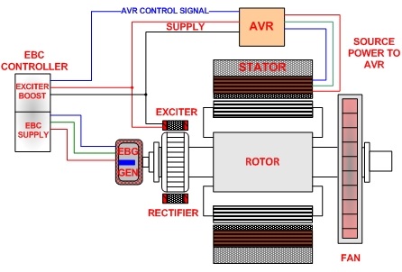 The line OA represents the shunt field circuit resistance. A circuit diagram with the open-circuit characteristics of separately excited dc generator is shown below: The armature is driven at rated speed by the prime mover and switch s is in the open position. For DC separately excited generator, we noticed the e ect of eld current and generator speed on the output voltage, and we studied about the load characteristics of this generator. Characteristics Of Separately Excited Dc Generator Electrical Simple from 3.bp.blogspot.com Because production models, such as the tesla roadster. Who are the experts? The external characteristic of a shunt generator can be obtained by conducting a load test on it in a manner similar to that described for a separately excited generator. Search for: Popular doubts. The regulator three phase power supply has been set to channel B (42V, 10 A) 3. The O.C.C. of a separately excited generator is determined in a manner described in the previous section. It shows the variation of generated e.m f. on no load with field current for various fixed speeds. Note that if the value of constant speed is increased, the steepness of the curve also increases.
  Find the torque constant for the machine Convert rpm to rad/sec Find the torque 7 Lesson 11 332a.pptx Example 11-2 Torque Constant (2) Remember B p is constant for constant The field excitation (If) is adjusted to give a rated voltage at no load. external characteristic. In order to determine the open circuit characteristics of a DC generator, the field winding is disconnected from the machine and is excited by an external DC source. Question: Procedures: Part 1: Separately excited de generator = No-Load Characteristic 1.1 Connect a de machine as a generator, and other de machine as a motor in accordance with circuit diagram (1) 1.2 Make sure that the switch S is off and the two regulators are turned to minimum value. Also, the terminal voltage is lesser due to ohmic drop occurring in the armature and brushes. A separately excited DC Generator with compensating windings is rated at 160 KW, 300 V, 200 A, and 1800 r/min. shows the operation of the machine as a separately excited AC and a separately excited DC generator where the armature voltage drop for AC generator is higher than the DC generator because of the armature reactance. Writing a voltage loop through the armature and field circuits as shown results in the following relationship: Ea = I The generator is run at its normal speed. Shuts off power at 103 volts (low) and 130 volts (high) The ITS-50R is designed with an easy-to wire bridge 4375 Watt Max Starting Extra Long Life Gas Powered Generator - EPA III Turn off the circuit breaker providing line power to the unit Separately Excited DC Generator Separately Excited DC Generator. flux is directly proportional to the field current. Remove the existing variable load torques and Before getting into the topic, be strong with the construction and working principle of DC Generator. Separately excited DC motor can operate above base speed. Separately excited DC generator. Types of DC Motors are classified into four major categories. armature circuit. The presence of residual flux is a must for self Describe how diesel engine output power relates to the power demands of the generator. The field winding of the machine requires a separate source to supply. #2 Separately Excited Generator. In separate excited dc generator the field current is kept as constant in case of self excitation field current is variable. In this, the magnitude of the voltage depends on the speed of rotation of the armature and the field current. Its shape practically the same for all types of DC generator whether separately excited or self-excited. Separately Excited Dc Motor - 17 images - electric motor, characteristic of dc generators separately excited self excited and compound generator, chopper control of separately excited dc motor circuit globe, types of dc (OR) A separately - excited dc generator is a dc generator whose field magnet winding current is supplied by an external dc voltage source. For comparison, a self- excited dc generator is a dc generator whose field magnet winding is supplied by current from the output of the generator itself. What DET 3043 ELECTRICAL MACHINES Lab 2 - DC Generator (Separately Excited) 1. If this generated voltage itself is used to excite the field winding of the same d.c. generator, it is called self excited generator. If the armature reaction is neglected, decrease in V a should be linear and equal to the voltage drop across R a and carbon brushes. The voltage of the generator is changed by changing the generator field current. Self-excited DC generator. Regulator Compatible. The RMS value of the voltage u(t) = 3+4cos(3t) is asked by editor;
This type is also called a servo type motor. Answer (1 of 2): In self excited DC generators field circuit is connected in parallel with armature circuit in the case of shunt generators and in series with armature circuit in the case of series generators. The connection diagram is shown below: In the above system, M is the main DC motor whose speed is to be controlled, and G is a separately excited DC generator. The Prime Mover of the motor connected in star connection as stated in figure 2 (Schematic diagram of Prime Mover).The cable used is The Power Supply Unit (DL 10281) has been ensured in OFF condition. Transfer function of separately excited dc generator How does a separately excited dc generator work. Separately excited. driven generator unit. What is separately excited dc generator. Explanation. It is supplied from a 120 V supply and draws 5.6 A. Effect of armature reaction on separately excited generator terminal voltage. Separately Excited DC Generators . The different types of DC motors are further classified based on the electrical connection between the rotor and stator and their ability to create field reflux.. Circuit Diagram for a generator voltage regulator. Throughout the operation, this value of voltage is kept constant. Engineering Electrical Engineering Q&A Library Draw the circuit diagram with the related equations of a separately excited DC shunt generator. Download scientific diagram | Circuit Diagram of Separately excited DC Motor from publication: Emulation of a Low Power Wind Turbine using DC Motor mechanically coupled to with 50% of rated load The system is located in De Kooy, a coastal location in the Netherlands, where the potential yearly energy production of the wind turbine is about 135 MWh/year (=15 kW average power) 8kW Generators have gained in popularity because they offer the same affordability of the 7kW line, but with an extra kW of running power, there is Self Excited Generator Honda Giken Kogyo Kabushiki Kaisha. 1. The three types of DC Motors are- Separately Excited, Self Excited, and Permanent Magnet. Based on the methods of interconnection of windings the following types of dc generators are available.(i). The circuit diagram of a separately excited DC Generator on loaded condition is shown below. It is supplied from a 120 V supply and draws 5.6 A. In separate excitation a separate dc source is needed for excitation purposes only and is obviously inconvenient. Self Excited Induction Generator Newcastle University. Separately Excited DC Generators . 1: (a) Load test on a separately excited d.c. generator, (b) Characteristics of a separately excited generator. We review their content and use your feedback to keep the quality high.
What Is A Separately Excited DC Generator Quora. Explanation. 3. So on this basis there are two types of DC generators:-. Test No.
The generator is run at its normal speed. The machine is driven at a normal speed and field current is adjusted to obtain rated no-load voltage. The field current can be varied by a variable resistance connected in series. The generator is driven by a prime mover at rated speed, say n rps. The d.c. generator produces d.c. voltage. In order to determine the open circuit characteristics of a DC generator, the field winding is disconnected from the machine and is excited by an external DC source. The results were recorded in the table and mathematical operations were done in order to get the appropriate graph of the results. Fig. (b) Series-field connection, and (c) Compound-field connection. 1.1 Magnetization or Open Circuit Characteristics. A DC motor is defined as a class of electrical motors that convert direct current electrical energy into mechanical energy. External DC source (e.g., battery) is used in this system for energizing field magnets. 1 DC separately excited generator 9 The comparison between the performance of DC generators and the static and induction loads can be made by simulating the below lab single line diagram. 2. The arrangement to obtain this characteristics is shown in the Fig. As with the DC motor, the shaft torque of the DC generator is countered by a force created at the stator mounting point. Thus a wide range of output voltage may be obtained. The characteristics is separately excited d.c. generator are divided into two types, 1) Magnetization and 2) Load characteristics. Hence, two DC supplies are required for its operation. The DC Motors have unique speeds and hence find Answer (1 of 8): The separately excited dc generator, the field winding is connected to a separate source of dc power. The arrangement to obtain this characteristics is shown in the Fig. 2.2 Separately excited DC motor in steady state 8 2.3 Torque vs speed characteristic for different armature voltages 9 2.4 Torque vs speed and power vs speed characteristic of separately 2.12 Block diagram of a two hidden layer multiplayer perceptron(MLP) 19 3.1 The block diagram of a variable speed neural network Separately 1 (a), the field being connected to a separate dc supply source. Figure 3: Circuit diagram for self-excited DC generator * Note down the DC generator ratings from the name-plate. Figure below shows the separately excited dc motor. A DC generator whose field winding or coil is energised by a separate or external DC source is called a separately excited DC Generator. The field of them does not need any separate excitation. A Self Excited Synchronous Generator For Small Hydro. This curve gives the relation between the terminal voltage (V) and load current. As the rotation speed increases, it can provide a higher EMF and voltage in the output. Fig. The connections are made as shown in Fig. Because it has a wide range of voltage input. 4.4. A voltage regulator for a separately excited generator including a main generator unit having generating winding means and exciting winding means and an exciter comprising a magnet field type generator with the output connected through a rectifier to said exciting winding means, said voltage regulator comprising thyristor means connected to said output of said exciter to short The voltage produced by the generator causes a current to flow in the relay coil. of separately excited generator. Learning Objectives As a result of this lesson, you will be able to: 1. Transfer function of separately excited dc generator How does a separately excited dc generator work. Figure 2: Equivalent circuit of a separately excited DC generator As the load current I L increases, the terminal voltage decreases as indicated by solid line. Separately excited motor have separate field winding means supply to armature is different and supplied to field is different. As the rotation speed increases, it can provide a higher EMF and voltage in the output. It is also used as a supply to DC motor. However, if the generator is operated at the knee point in the magnetization Its shape practically the same for all types of DC generator whether separately excited or self-excited. 1 (a). 2. 2. The curve AD represents the terminal voltage vs. load current i.e. 2. At no-load, the terminal voltage of the generator will be constant (= External Characteristic of Separately Excited DC Generator The external characteristic of the separately excited DC generator is obtained by subtracting the drops due to ohmic loss (Ia Ra) in the armature from generated voltage (Eg). Describe the functions of the generator, exciter, and voltage regulator. Download scientific diagram | Separately excited dc generator equivalent circuit from publication: Estimation of the power coefficient in a wind conversion system | In External DC source (e.g., battery) is used in this system for energizing field magnets. The total armature circuit resistance is .473 ohms. No load or Open circuit characteristic: In this type of generator field winding is excited from a separate source, hence field current is independent of armature terminal voltage as shown on figure (A). DC-Separately Excited Generator Instructor :Dr. Mohamed Al-Wedyan Lap supervisor : Eng.Majid Al - Briqi Bahaa Ishaq 833150 . Also draw the open circuit characteristics. The connections are made as shown in Fig. Self-exicted dc Generators with (a) Shunt-field connection. External Characteristic. The performance of a separately excited DC generator is analyzed with the help of three different characteristics: Magnetic or no-load or open circuit characteristics, internal or total characteristics and external characteristics.
separately excited generator diagram