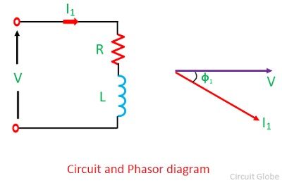
 For example, if you need to change some capacitors in the bank, or add some more, in the parrallel series all you need to do is disconnect the bank from the rest of the network, rather than the whole facility, if you had connected them in series. The LV side of the transformer along with the power factor correction capacitor behaves as a parallel resonating circuit at resonating frequency the impedance offered is very high consequently the harmonic current causes an increased harmonic drop which may be accompanied with distortion of the fundamental. Thus the p.f is improved. For Hope this helps. Abstract: Power factor correction is an important facet of power quality. Power Factor Correction. In AC power supplies Capacitor Banks are mainly used to improve the power factor of the AC Loads. In the simplest case, an appropriately sized capacitor is installed in parallel with each individual inductive consumer. Search: Capacitor Sizing Calculator. Power factor can be corrected by connecting a static capacitor in parallel with the load taking lagging reactive power. The nominal voltage drop upon those series capacitors, ranges between 10-20% of the nominal transmission voltage. The power factor calculation does not distinguish between leading and lagging power factors. so a reservoir capacitor is connected in parallel to the diode bridge to help smooth the output voltage ripple. Regarding power systems: Actually you can, and you will improve the power factor in the same way. The following may be deduced from this vector diagram: V2 and node numbers: 0, 1, 2, and 3 are SPICE related, and maybe ignored for the moment. It absorbs and generates the reactive power (Var) by varying the excitation of the motor field winding. Although power factor correction capacitors can considerably reduce the burden caused by an inductive load on the supply, they do not affect the operation of the load. This method features lower installation cost and provides compensation of the total PF of entire facility. The power factor correction calculation assumes inductive load. For some applications, correcting the power factor in an AC circuit can be as simple as adding a capacitor in parallel with the electrical load. Capacitors provide capacitive or leading reactive power that cancels out the lagging reactive power when used for The power factor correction capacitor will have the full supply voltage across it so it will cancel most of the inductive component. An 80 F capacitor will have a capacitive reactance of 33.157 , giving a current of 7.238 amps, and a corresponding reactive power of 1.737 kVAR (for the capacitor only ). capacitor provides reactive power locally to load instead of getting from generators or power system which in return induces burden in power system. For power factor improvement, capacitors are connected parallel in the circuit. when inductive load is high and lagging current is high, these capacitors when connected in prallel draw leading current which improves the power factor. Capacitor bank can also be connected in series but the desired effect will not be acheived. Power-factor-correction capacitors are used for this purpose. First thing - the capacitors do not change anything in the motor itself with the exception of maybe some improvement in voltage drop, which would result in less current being drawn. Figure 5 - LCD (Inductor/ Capacitor/ Diode) Power Factor Correction The first electrolytic capacitor is the most likely to fail in this circuit, because it has a high ripple current. Power factor correction Power factor correction is the term given to a technology that has been used since the turn of the 20th century to restore the power factor to as close to unity as is economically viable. useful power and total power = cos .
  Steelman capacitors are built with components that meet or exceed industry standards. Applications. This is referred to as harmonic resonance or parallel resonance. Capacitors are devices used to store electrical energy in the form of electrical charge. The modern capacitor is a reliable, maintenance free cheap source of VARs needed in inductive circuits to synchronize the voltage and current waveforms.
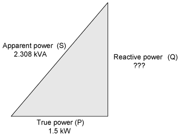
Shunt capacitors are often used to improve power factor. Power Factor Correction (PFC) targets to improve power factor which in turn controls the power quality, utilising capacitors to offset usually inductive loads. Power factor correction is a technique of improving the power factor of Electrical system near to unity (1) by using extra electrical equipment which can absorb or supply reactive power to the circuit. It is often possible to adjust the power factor of a system to very near unity. The synchronous condensers are the most used power factor improvement devices and the exciters in the power system. Power factor correction is achieved by the addition of capacitors in parallel with the connected motor or lighting circuits and can be applied at the equipment, distribution board or at the origin of the installation. Obtain an expression for the complex power of load "B": Apply the law of conservation of AC power to get the complex power of the circuit: $$ P_f = 0.899 $$ B) Determine the capacitor value required to correct power factor to unity: In order to get a power factor of "1" we need the new power factor angle to be 0 degrees (cos[0]=1). Power factor correction is the method to reduce the lagging power factor in inductive loads by fixing a high value capacitor across the phase and neutral close to the load.  4.Under rated voltage and 20 temperature ,the tan of loss angle of capacitor is as follows: 1)No more than 0.0022 for low-voltage film-paper parallel capacitor. The diagrams below show capacitor connections for typical starting circuits for reduced voltage motor controllers. As such, power factor correction through the application of capacitors is widely practiced at all system voltages. 2) No more than 0.0015 for film parallel capacitor. Capacitors Used in Series and Parallel Power Factor Correction (PFC) targets to improve power factor which in turn controls the power quality, utilising capacitors to offset usually inductive loads. This effect is used in some applications. #4. Static power factor correction can be applied at each individual motor by connecting the correction capacitors to the motor starter. Mar 2, 2012. The use of capacitors has long been accepted as the most practical solution to the low power factor problem in power systems. As a capacitor is generator of reactive power, therefore the lagging reactive power demand of the equipment is locally supplied by the static capacitor. A system and method for dynamically adjusting capacitance added in parallel to an electrical line input for improving efficiency of an electrical system. Note however that the caps reduce only upstream reactive power. For some applications, correcting the power factor in an AC circuit can be as simple as adding a capacitor in parallel with the electrical load. Recall the formula for the capacitance value The change in properties to the circuit (due to the capacitor) are represented in the following phasor diagram: The voltage drop is not so much of an issue. This relation shows that the power taken from the supply has not altered. Power factor correction capacitors increase system current-carrying capacity. Power sources are available in which the capacitor is incorporated in or attached to the welding transformer. low-voltage power factor correction capacitors and the requirement for high output density results in reduced ohmic resistance in PFC capacitors. The power factor measures the amount of energy used for a given supply from the utility company. The simple, single-phase transformer welding source lends itself readily to power-factor correction by the connection of a capacitor on the primary side. The power factor correction capacitor should be connected in parallel to each phase load. The power factor calculation does not distinguish between leading and lagging power factors. The power factor correction calculation assumes inductive load. Power factor calculation: The use of capacitors has long been accepted as the most practical solution to the low power factor problem in power systems.
Benefits of Inverters with Power Factor Correction. Power factor correction (PFC) is the series of methods used to try to improve a devices power factor.
Correctly Sizing capacitor panels accurately is a skill Published on Nov 6, 2015 These simple method to calculate required electrical power factor correction and improvement, we essential to know The limiting factor for the size of capacitor is the power supply (PSU) you intend to use Dropping Resistor Calculator (The Calculator is at the bottom of the page if you That is higher the phase angle or phase shift lesser the pf. The non-linear loads in the increased complex networks adds a significant amount of burden to the network. Capacitors Power Factor Correction So a power factor correction device typically includes nothing but a capacitor that is to be connected in parallel as the additional load. So, to correct the power factor, an ideal parallel capacitor will simply make $$\operatorname{Im}\left(\frac{Z_CZ_L}{Z_C+Z_L}\right) = 0 \Longrightarrow C=\frac{L}{\left|Z_L\right|^2}$$ for a new total impedance of $$\left|\frac{Z_CZ_L}{Z_C + Z_L}\right| = \frac{\left|Z_L\right|^2}{R_L} > \left|Z_L\right|$$ which means we'll draw less When capacitors are added in parallel to the inductive load, the inductive e ect will be cancelled out. By connecting capacitor banks parallel to load, power factor is increased. The synchronous condenser was running without the mechanical load, and it is connected in parallel with the load. The motor power factor has to be improved to 0.94 by connecting capacitor bank across it. Figure 1 Power factor correction principle. The non-linear loads in the increased complex networks adds a significant amount of burden to the network. Figure 5 - LCD (Inductor/ Capacitor/ Diode) Power Factor Correction The first electrolytic capacitor is the most likely to fail in this circuit, because it has a high ripple current. Make sure that the circuit matches the actual motor diagram before applying capacitors. Phase advancer is a basic exciter that is used to increase the power factor of the induction motor. The motor power factor has to be improved to 0.92 by connecting a capacitor in parallel with it. The Power factor decreases with an increase in lag or lead of current from the voltage. This practice is known as power factor correction and is achieved by switching in or out banks of inductors or capacitor banks. Actually, the concept behind the power factor correction is Reactive power compensation technique, which can be done by using a capacitor bank and synchronous condenser in parallel to the circuit. This in effect increases the power factor by bringing it nearer to unity. I loaded a 5uF/450V capacitor to the same power outlet & the power factor increases to 0.82 & the current takes drop down to 770mA. It also gives the equivalence between cos and tg . In order to improve power factor, some devices taking leading working power should be connected in parallel with the load. When we read the power transmission or Circuit Theory,the book will teach us two things 1.we can connect the capacitor in parallel to improve the power factor 2.we can connect the reactor in parallel to avoid the increasing of voltage This results in the decreased power factor.
When apparent power (kVA) is greater than working power (kW), the utility must supply the excess reactive current plus the working current . 3) No more than 0.0008 for high-voltage film-paper parallel capacitor. Share In the past, the application of capacitors was However, Power Factor Correction (PFC) procedures can keep the power factor within an acceptable range. Without a line voltage (230V/50Hz) parallel capacitor, my refrigerator shows Power factor = 0.62 & It takes current exactly 1A. The power factor can also be correct by installing the specially designed induction motor, known as the synchronous condenser. By connecting a capacitor in parallel with an inductive load, the power factor is improved, and the current from the supply is reduced without altering either current or power taken by the load. Shunt Capacitors in Improving Power Factor of Load Inductive components of a power system draw a lagging reactive power from the supply. A microprocessor monitors in real time the current and voltage wave forms of a system and selects the optimum amount of capacitance from a bank of capacitors of different values. Steelman Capacitors are engineered for heavy-duty, trouble-free use. The synchronous condensers are the most used power factor improvement devices and the exciters in the power system. This is a simple means of calculating the required size of the input filter capacitor in a basic power supply, or calculating the peak-to-peak ripple voltage in an existing supply Factors that affect the selection of the proper voltage rating of the Use the equation below to verify the size of the capacitor Actual power factor, peak The standard also states that the VA rating of the capacitor The system is implemented at the watt-hour Parallel capacitor corrects lagging power factor of inductive load. Security of supply Reduction in peak currents prevents fuse failure and loss of supply. Extend of lag of a circuit that operates in lagging power factor is considerably reduced by connecting capacitors in parallel to that circuit.
power factor correction capacitor in parallel